Share
Pin
Tweet
Send
Share
Send
Of course, this is not difficult for an experienced grinder even with manual work. It will not be easy for everyone else to withstand the required sharpening angle. Is it possible for them the problem of blunt knives will remain unsolvable?
There are three ways out of this predicament: learning to sharpen knives, but it will take a lot of time, patience and effort; each time ask a professional for help and pay for his expensive service; make the knife sharpener itself and not think about the angle of sharpening.
Below we will consider a method of manufacturing a device for sharpening knives based on an electric sharpener with two abrasive wheels.
Will need
So that the work does not take a lot of time and energy, it’s good to have in stock: a welding machine, machines (drilling, milling and turning), a pendulum saw, drill, grinder, wrenches, marking tools, etc.
From materials and components, in addition to the already mentioned electric sharpener, it is necessary to stock up:
- a metal sheet 10 mm thick;
- square tubes (two pieces of adjacent sizes);
- round metal rod up to 400 mm long and 15-20 mm in diameter;
- threaded fasteners (bolts, nuts, washers), etc.
Making knife sharpener
The work will consist of two relatively independent stages: the arrangement of an electric sharpener and the manufacture of a knife holder that provides the required sharpening angle.
Sharpener arrangement
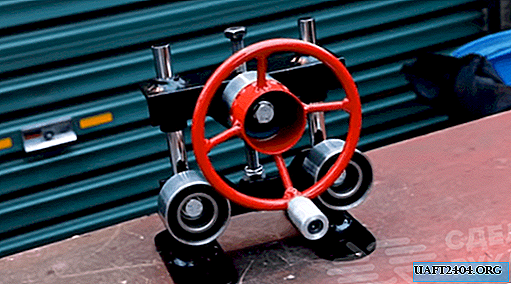
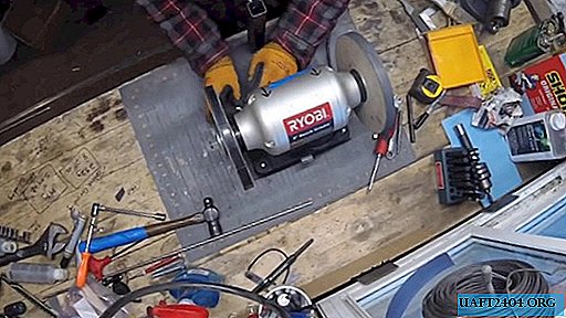
One of the necessary conditions for high-quality sharpening of knives is the stability of the grinding tool. Therefore, we use a metal sheet suitable in size and thickness as the base for the electric sharpener.

Using a tape measure, core and hammer, we mark the centers of the four holes, repeating the holes on the electric sharpener plate. We drill holes according to the marking on the drilling machine and, using bolts and nuts, we fix the electric sharpener on a metal base.

We cut off with a pendulum saw two pieces of square pipes previously calculated along the length, moreover, one must freely, but without a large gap, enter the other.

In a pipe of a smaller cross section, a through hole is milled from one end, the diameter of which should be slightly larger than the diameter of the metal rod. In the second pipe, we also plan and drill a hole for the locking bolt from one end.

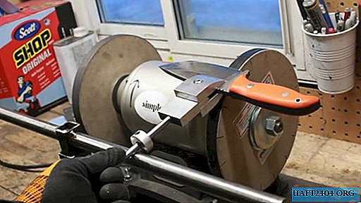
We weld a pipe of a larger cross section in the center to the base, opposite the fixed sharpener, in such a position that the fixing bolt looks outward and is on top. To prevent drops of molten metal, sparks and scale from welding from damaging the electric motor, we cover it with a welding blanket.

We insert the rod strictly to the middle into the drilled hole in the pipe of a smaller cross section and weld it in this position to the pipe, having previously checked the perpendicularity of these mating parts with a right triangle.


If this has not been done in advance, remove the electric sharpener from the base and revise the electric box, then re-install the sharpener in place and check its operability.
We insert the pipe with the rod into the pipe welded to the base and with the help of a bolt you can set the required height for sharpening a specific knife. This was the last stage of arranging an electric sharpener. Getting to the second phase of work.


To the electric sharpener, we change the direction of rotation.

Making a knife holder
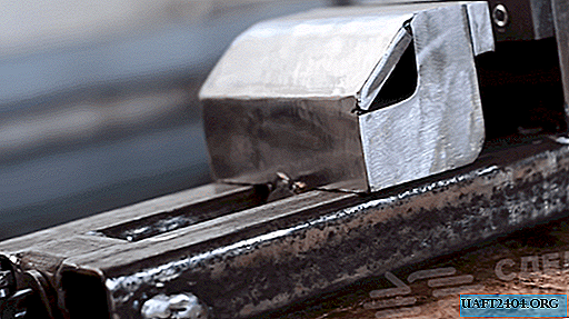
As already noted, the quality of knife sharpening, first of all, depends on ensuring the constancy of the angle of sharpening. The holder we are going to make is just for this.
We mark the metal workpiece in accordance with the intended dimensions of the three elements, which will ensure the capture and reliable retention of the knife blade at a given angle to the surface of the circle when sharpening.

We cut them with a pendulum saw with the addition of lubricant to improve the quality of the cut and the safety of the saw blade.
We clamp all three elements in a “vise” into the vice of the milling machine and process the surfaces to the required size and with each change of position we remove the burrs with a hand file.


On two workpieces we form jaws for gripping and holding the knife blade. For this, each of them is milled to their size on one side. The third workpiece is milled on both sides to the size. It will serve as the basis for securing to her lateral grips with jaws.

On the part that will be in the middle, on the milled part, we mark out two holes located symmetrically to the longitudinal axis closer to the edges and slightly offset to the base. We drill them on a drilling machine.
Using this part as a sample, mark the response points on two other blanks with a drill and a thin drill.
Then we drill the marked spots with a large diameter drill to a shallow depth (we make, sort of, nests-recesses).
We screw into the holes of the central element, two pins of the required length with the same output, which, when installing the side elements, will go into the recesses and hold them, but do not interfere with the jaws, converge and diverge.
In the lateral jaw elements in the geometric center, we outline and drill holes of the same diameter and cut the threads into them with a hand tap.
We milling the outer edges of the jaws to complete the appearance of the device and ease of operation. We also remove the chamfer on both sides of the milling end of the central element so as not to interfere with the adjustment of the jaws.

In the center of the base of the central element, we outline and drill a blind hole for the mandrel.

We mix two-component glue and fix with it the mandrel of the required length in the blind hole. Let the compound seize and harden. To do this, we fix the central element with a mandrel in a wooden vise.
We clamp a metal bar of the calculated diameter in the lathe chuck and drill a hole in the center slightly larger than the diameter of the mandrel, periodically adding grease to the drilling zone.
Then cut off a cylinder with a height of about 10-12 mm and drill a hole on the side surface, followed by threading with a tap for a locking screw.


On one of the side elements from the outside, drill a central hole to install the bolt head flush.
Finally we finish the surface of the fixture by processing on the grinder, first with an emery endless tape, and then with a nap tape.


It remains to assemble the elements of the adjustable holder together by screwing the connecting bolt into the jaws and securing the cylindrical ring on the mandrel, installing it in the right place with the locking screw.
Fixture test
We hold the knife blade in the jaws of the holder and set the required height of the transverse rod and the length of the mandrel by moving the cylindrical ring down or up and locking it where necessary with a special screw.
In order for the sharpening angle to remain the same along the entire length of the blade, it is sufficient to ensure the sliding of the cylindrical ring fixed on the mandrel over the surface of the rod mounted horizontally in front of the circles of the electric sharpener.


After a short sharpening without any tension, the knife easily cuts a sheet of writing paper by weight, which confirms its excellent sharpening.


Share
Pin
Tweet
Send
Share
Send